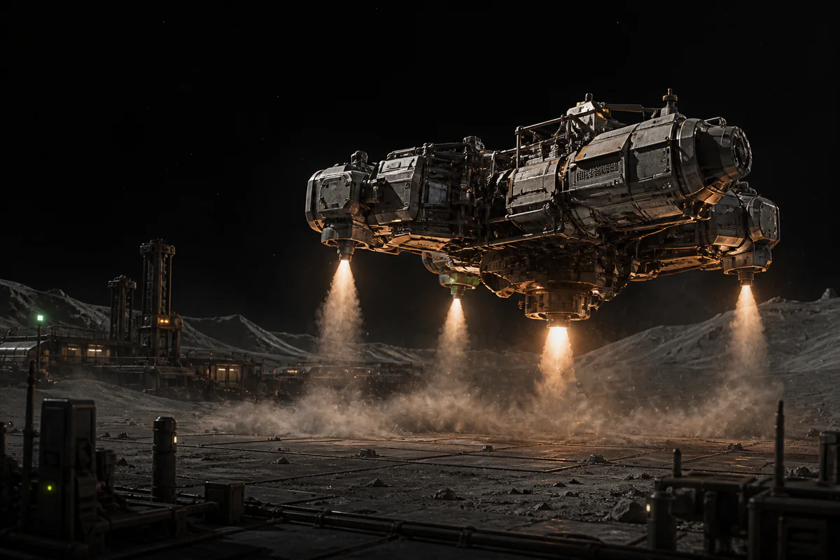
To build a ship in Approximately Up, start with a symmetrical, inspectable frame, keep its center of mass visible as parts are added, and connect one controllable subsystem at a time. Leave the cockpit and cable routes open until RCS, lift, and directional thrust each respond correctly, because a closed hull can hide a bad port or loose attachment. Treat every key prompt and component behavior below as an observation from the collected tutorials, then verify it against the current game build and the prompts on your screen. The goal is a modest craft whose structure, signals, and motion you can explain before expanding it.
Verify the parts and current controls
Check the current inventory and in-game manual before placing the first structural part. The tutorials use a frame, seat or cockpit area, a control device, an RCS controller and thrusters, batteries, power and data cables, plus separate lift and directional-thrust parts. Your progression state may expose different variants or quantities, so choose by the labels and functions visible now rather than copying a demonstration mechanically. Keep each system grouped near the pad until you are ready to install it.
The first tutorial observes prompts for selection, duplication, placement, inspection information, the manual, and simulation or flight mode. Those prompts are useful clues, not permanent keyboard rules, because bindings and interfaces can change between builds or after customization. Rehearse the building loop with one disposable part: read the visible prompt, place and inspect it, then move or remove it using the controls your game displays. That confirms the current workflow without turning an old transcript into an unsupported control guarantee.
Build a symmetrical, inspectable frame
Lay out a center line and extend matching structural shapes on its left and right sides. The collected tutorial copies and rotates selected frame sections to create repeated geometry, but its exact selection and confirmation prompts must be checked in the current interface. Mirror changes in small batches, then compare both sides from the front, rear, top, and underside. A paired structure gives you reliable reference points when balance or attachment behavior becomes uncertain.
Keep at least one service side open while the cockpit, controller, and main cable routes remain unfinished. A sealed shell can conceal ports, force cables around awkward obstacles, or require structural removal to inspect one connection. Reserve reachable space behind and below the controls, and make substantial additions such as armor or batteries in matching positions when the design permits. If the sides no longer correspond, correct the frame before more systems make the cause difficult to isolate.
Track the center of mass as the ship grows
Use the current build's inspection or debug view to locate the center-of-mass marker after the bare frame is stable. The transcript observes a key prompt for this view, but follow the prompt and settings shown in your version instead of assuming the same binding. Note where the marker sits relative to the center line, cockpit, and planned thruster mounts. This reference is more useful than a demonstrated mass value because your own parts and layout define your balance.
Recheck the marker after each meaningful group: cockpit equipment, batteries, armor, RCS hardware, lift devices, and directional thrusters. If it shifts unexpectedly, compare the sides for a missing counterpart, different orientation, or unequal distance from the center line, then adjust that group before continuing. An off-center thrust line is also a possible cause when the craft rotates during intended translation or lift, although the full build determines the response. Never adopt sample mass, thrust, or spacing values from either tutorial as universal targets.
Assemble the cockpit and RCS control path
Place the seat or cockpit controls where their rear ports remain visible from the service area. The tutorials connect a control device to an RCS controller, provide the controller with power, and route its output toward configured RCS thrusters. Build that traceable chain before adding unrelated devices, and label the control if the current component supports labels. You should be able to follow pilot input through the controller to every intended endpoint without guessing which cable is which.
Configure RCS for the rotations the craft needs, using the current manual and component interface to verify pitch, yaw, and roll behavior. Demonstrated positions and modes are examples because orientation and placement relative to the center of mass can change the result. Configure one paired direction, test it gently, and change the setting or position only after observing your craft's response. The first RCS test must also confirm that each component remains physically attached when simulation begins.
Place lift and directional thrust deliberately
Add lift only after the center-of-mass reference and RCS path are understandable. Put lift devices in matching, inspectable positions, keep their ports accessible, and inspect the marker again because new hardware can alter balance. A front-and-rear or left-and-right arrangement shown in a tutorial is only an example for that hull. Evaluate your placement by its symmetry, attachment, relationship to the current marker, and observed low-risk behavior.
Treat forward, reverse, and other directional movement as a separate subsystem from lift. Arrange each intended thrust line deliberately around the center of mass, then consider an offset as one possible cause if translation introduces rotation. Some demonstrated parts can alter how an input is interpreted, but their labels and behavior are version-dependent, so read the live component panel before selecting a mode. Before wiring everything, briefly enter simulation near the pad and fix any part that drops, shifts, or separates.
Wire power and data as separate testable systems
Trace power and data as two jobs even when their cables travel near each other. In the collected tutorial, power forms a shared circuit while data follows a direction from a control output toward the input that consumes the signal. The transcript also observes color-coded ports, but colors, labels, and connector behavior must be checked in the current build. Follow live port cues and the manual rather than relying on color memory alone.
Wire the cockpit and RCS chain first, lift second, and directional thrust last. After each chain, follow it from source to destination, confirm required power, and keep bends, crossings, and ports visible until the subsystem passes. If nothing responds, check attachment, power, and each data handoff in that order; if the response is wrong, inspect controller assignment and component orientation. One known input and one expected response create a much clearer diagnosis than connecting the whole craft at once.
Run a low-altitude test and save a baseline
Move the starter craft close to the pad and enter the current build's simulation or flight test using the prompt displayed on screen. Begin with a small input and remain in a low-risk area where an unexpected roll, yaw, or loose part can be observed without making the test a performance attempt. Check attachments first, RCS rotation second, lift third, and directional movement last, expressing only one control intention at a time. Return to construction as soon as one response differs from the intended response.
Change only one attachment, cable, orientation, or setting before repeating the same test, then compare unwanted rotation with the center-of-mass marker and thruster position. Once every subsystem produces the expected basic response, record the verified part positions, cable paths, orientations, settings, and current-build bindings as your baseline. Use that record to compare later changes when adding armor, automation, mission equipment, or a larger power arrangement. A reliable first ship is one whose verified configuration you can inspect and explain.